Bridges & Trestles
At this point, the SCLCo sports a single bridge in the form of a trestle. A second bridge is planned for Mick-elangelo Falls.
The reasons for the trestle were
two-fold. First, I wanted one. ![]() Second,
the garden plants were in almost a year before the railroad, and
couldn't, according to the Local Conservation Authority (namely,
my wife), be disturbed/dug up/overshadowed/killed or in any way
damaged. A patch of Myrtle about six-feet wide had been planted
under a trio of Cypress trees, the only original thing left after
the back yard makeover. The need to go over this Myrtle patch
with minimum disturbance, combined with reason No. 1, provided
all the justification needed for the trestle. Since the length of
the span was 120 feet (6'), with an average height of 12-1/2 feet
(7-1/2"), company management agreed, and decided a trestle
would be an ideal solution.
Second,
the garden plants were in almost a year before the railroad, and
couldn't, according to the Local Conservation Authority (namely,
my wife), be disturbed/dug up/overshadowed/killed or in any way
damaged. A patch of Myrtle about six-feet wide had been planted
under a trio of Cypress trees, the only original thing left after
the back yard makeover. The need to go over this Myrtle patch
with minimum disturbance, combined with reason No. 1, provided
all the justification needed for the trestle. Since the length of
the span was 120 feet (6'), with an average height of 12-1/2 feet
(7-1/2"), company management agreed, and decided a trestle
would be an ideal solution.
A trestle was forthwith designed, based upon prototype practices explained in Kalmbach's "Model Railroad Bridges and Trestles." Materials were ripped from Redwood Select 2x4's in the local sawmill (on my table saw), and construction proceeded apace. Total construction time from start to finish was two weeks.
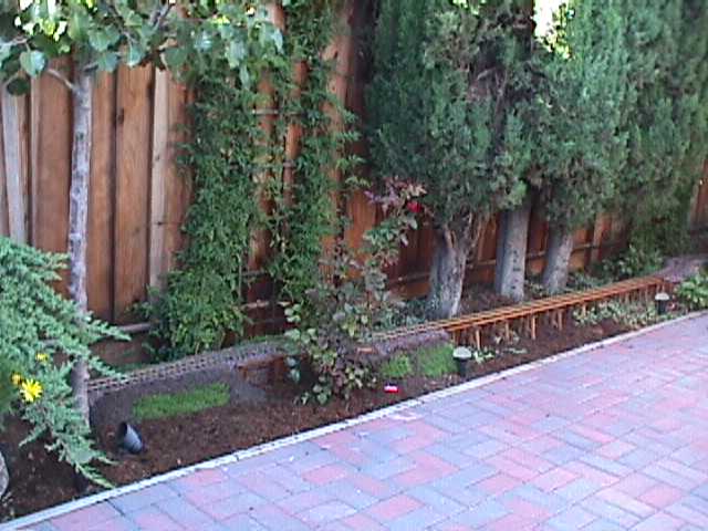
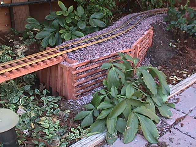
An overall shot, which shows the curved approaches on each end
needed to traverse the area with no disturbance to surrounding
vegetable matter.
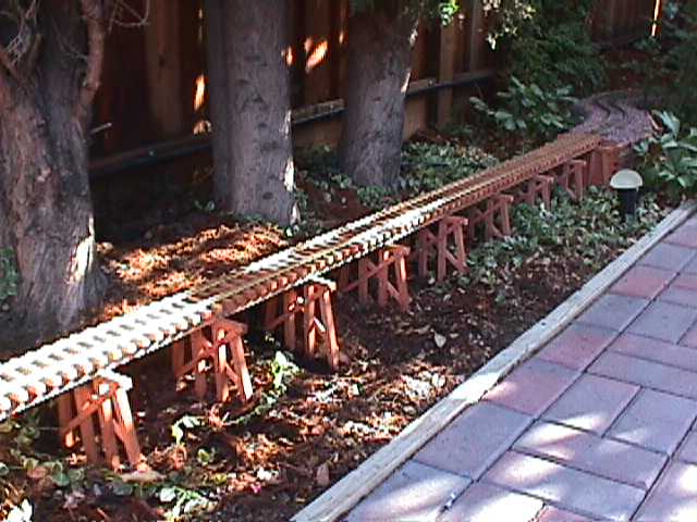
A closer overall shot. The Myrtle has really filled in since this
was taken.
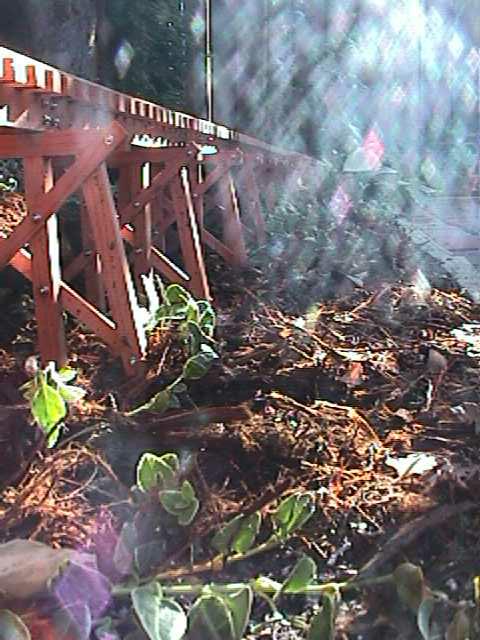
I really like this photo, though the final result was unplanned.
Actually, I'd have preferred a pile trestle, but couldn't find
5/8" redwood dowel, and I didn't feel like trying to turn it
down. My justification for posts instead is that old growth
redwood trees don't grow in a diameter suitable for piles, so the
SCLCo
opted for rough-sawn posts from its own mill.
Bents were constructed in a jig using carpenter's glue. When the
glue was dry, they were removed from the jig, drilled, and bolted
together using 4-40 stainless steel threaded rod cut into
one-inch lengths at each sway-brace/post intersection (eight per
bent). The nuts used were special small-pattern stainless steel
jobs I snagged from work from a job we no longer build. Caps and
bottom sills were pinned in place with 1 x 18 brass escutcheon
pins in pre-drilled holes. The deck (rails, ties, and stringers),
was installed first, then clamped to a 2 x 2 x 1/8 wall steel
rectangular tube borrowed from work to keep it straight and
level. Trenches were dug under each bent location, bents clamped
to the deck, and the trenches filled with mortar to completely
cover the bottom sills. Once dry, this prevents the bents from
moving. The trenches were then filled in, covering the mortar,
and giving the illusion that the posts are driven into the
ground.
The
aforementioned Local Conservation Authority had two Paeonia
(peony), plants (actually three, but only two figure into this
discussion), which are planted according to Feng Shui, an ancient
system which, among other things, tells ya where to plant stuff
for certain spiritual results. Accordingly, removal or
disturbance of these plants would be upon pain of death. These
were right where the eastern approach needed to be located. To
get between these prized examples of vegetable magnificence, the
railroad was obliged to build a retaining wall. A cribbed wall
was considered best from both an aesthetic and materials point of
view.
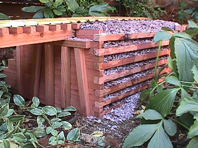
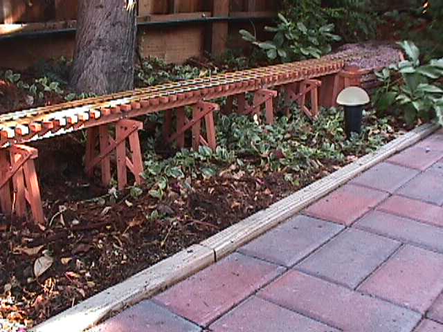
A close-up of the eastern bulkhead.
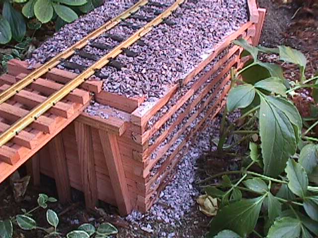
And another. Plastic lawn edging stapled to the plywood roadbed
was used to eliminate having to fill the entire space with
ballast.
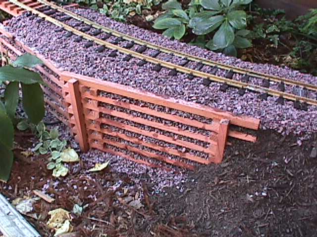
And a view looking somewhat North of West.
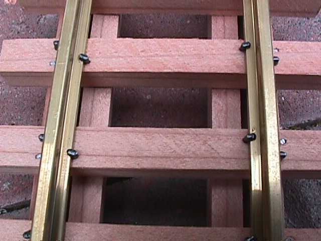
Rail was hand-spiked to individual ties for the trestle. I
dislike flex track or sectional track ties used on bridges or
trestles, since there's no ballast to "hide things."
Ties were also ripped to size, and fastened to stringers using
glue and, in this case, 5/8 x 20 stainless steel escutcheon pins.
Rail spikes are Micro-Engineering.